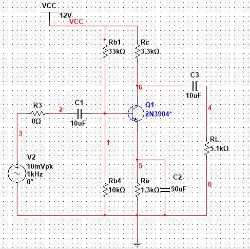
The 2n3904 experimental circuit is shown in the figure: (Note that the simulation circuit must be grounded!) Note that there is an AC_POWER, here I choose Vpk- as the peak value. Pay attention to the distinction, Vpp-peak-to-peak value, the voltage between two peaks. Vpk-peak value, voltage from peak to neutral Vrms-effective value The transistor used in the experiment is , so it needs to be changed before we use. 2N3904 BF is what we call the current amplification factor beta 1. Analysis of DC bias point (static operating point) In fact, it is some static parameters. . . We can use an oscilloscope or a multimeter to measure it, but the method here is more advanced. . . Enter the voltage and current to be observed Operation of DC SWEEP 2. Time domain analysis (analyze output waveform) Then we simulate You can click cursor -> show cursor to view the corresponding point data How to calculate the corresponding magnification? The peak value of our input signal is 10mv, then the peak-to-peak value of the input signal is 20mv For the output signal, we can add two absolute values of y, and we can get about 1.91V Then the voltage magnification of the circuit is 1.91/0.02 = 95.5 times 3. AC scanning (analysis of frequency response) Amplitude frequency and phase frequency 4. Parameter scan (analysis of bypass capacitor) 5. Conclusion The bypass capacitor only affects the lower limit frequency of the BJT circuit, and has no effect on the upper limit frequency. When the bypass capacitor is larger, the lower limit frequency is smaller.